FOR FLIGHT SIMULATOR USE ONLY. NOT FOR USE
IN REAL AVIATION. Level-D Simulations 767-300...........Page
31
ELECTRICAL SYSTEM
| <<TOPページ | <Level-D 767 メニュー | <マニュアル目次 | <前のページ | >次のページへ |
ELECTRICAL SYSTEM
電気システム
Electrical power is available from four sources:
aircraft battery, auxiliary power unit (APU),
external power, and two engine-driven generators.
航空機の電力には、航空機バッテリー、補助動力ユニット(APU)、外部電源、2つのエンジン駆動発電機の4つの電源があります。
AC and DC electrical buses distribute power
to various aircraft systems.
航空機各部への動力はACバスとDCバスを通じて供給されます。
Power distribution is handled automatically
via a bus tie system based on a priority
order.
通常パイロットの行う作業は、APUか、地上の外部電源を選択することことに限定されます。
Pilot interaction is normally limited to
selection of the APU and external power on
the ground.
Battery Power
バッテリー電源
The aircraft battery is controlled via a
latch switch at the top of the electrical
panel and is left in the ON position for
all normal operations.
航空機のバッテリーは電気パネルの最上部にある保護付きスイッチによって制御されます。そしてこのスイッチはすべての作業時にONにしておきます。
The battery provides basic DC power to essential
systems when no other power supply is available.
バッテリーは、他の電源がいずれも供給不能のときに、航空機の重要なシステムにDC電源を提供します。
When selected ON, battery power is supplied
via four buses: Hot Battery Bus, Battery
Bus, Standby AC Bus and Standby DC Bus.
バッテリー電源がONとされたときは、ホットバッテリバス、バッテリバス、予備ACバス、予備DCバスの4つのバスから電源が供給されます。
These buses power essential aircraft components
such as emergency equipment, radios, and
standby instruments.
これらのバスにより、航空機飛行に必須の緊急装置、無線機、予備計器に電源が送られます。
If no other power source is available, the
battery can provide power to these systems
for about 30 minutes.
もし他の電源が使用不可能なときは、バッテリはこれらのシステムに約30分間、電力を供給できます。
The MAIN BAT DISCH annunciation indicates
that the battery is being discharged.
このとき、MAIN BAT DISCH 表示が、バッテリー放電中であることを示します。
Power supplied to the Standby Buses is determined
by the Standby Power Selector.
予備バスへの電源供給は 予備電源セレクタにより指定します。
Control is provided by a three position rotary
switch with OFF, AUTO and BAT positions.
この予備電源セレクタは、回転スイッチになっていて、OFF,AUTO,BATの3つの項目を選択できます。
This additional control over the Standby
Buses is important because these buses provide
power for the standby flight instruments
as well as some basic warning circuits.
この予備バスに追加される制御は重要です。これらのバスは予備飛行計器と基本的な警報回路に対して電源を供給するからです。
In the AUTO mode, power is supplied to the
standby buses automatically based on priority
(battery being last) .
AUTOモードでは、優先順位に基づいて自動的に予備バスに電源が供給されます。(バッテリーが供給可能な限り)
With the selector in BAT, the battery alone
supplies power to the standby buses and the
battery will discharge (even if other sources
are available).
セレクタがBATとなっていると、たとえ他の電源が供給可能であっても、バッテリ電源だけが予備バスに供給され、バッテリは消費されていきます。
With the selector OFF, the standby buses
are not powered.
セレクタをOFFにすると、予備バスには電源が供給されません。
The selector is placed in the AUTO mode for
normal operations.
セレクタは通常操作のためにAUTOの位置になります。
The other modes are used for non-normal operation
of the electrical system.
他のモードは電気系統の非常操作に用いられます。
The following is an abbreviated list of important
equipment powered by the Battery and Standby
Buses:
次のリストはバッテリと予備バスによって電力が供給される重要な設備・機器の簡単なリストです。
| Battery Bus: バッテリーバス - APU Fuel Pump APU 燃料ポンプ - Engine and APU fire detection エンジン、APU火災検知器 - Engine fuel valves エンジン燃料バルブ - Bleed valves ブリードバルブ - Engine start controls エンジンスタートコントロール - Fuel crossfeed valves 燃料供給切替バルブ - Fuel quantity gauge 燃料量計器 - RAT auto deployment system RAT自動展開システム - Standby engine indicating 予備エンジン表示計器 |
Standby Buses: スタンバイバス - Bleed isolation valves ブリードエア分離バルブ - Manual cabin pressure control キャビン圧手動コントロール - Standby Altimeter, attitude and ILS 予備高度計、姿勢指示器、ILS - Pressurization indications 加圧表示器 - Left VHF radio 左側VHF無線機 - Left NAV system (VOR, ADC, RDMI) 左側NAVシステム(VOR,ADC,RDMI) - Standby ignition 予備起動装置 - Center ILS receiver 中央ILS受信機 |
|
| Hot Battery Bus: ホットバッテリーバス - APU fuel valve APU燃料バルブ - Fire bottles (engine and APU) エンジンとAPUのファイアボトル - IRS backup system IRSバックアップシステム - RAT manual deployment RAT手動展開システム |
Auxiliary Power Unit (APU)
補助動力装置(APU)
The APU is a gas turbine engine located in
the tail section of the aircraft.
APUは、航空機後尾に設置されているガスタービンエンジンです。
The APU can be used on the ground or in flight
to provide electrical and pneumatic power.
APUは地上または飛行中に電力と圧力空気を供給するために使用します。
The APU can satisfy the demand of all electrical
systems.
APUはすべての電気系統からの電力供給要求に対応できます。
The APU is normally used when the aircraft
is at the gate and for starting the engines.
APUは普通、航空機がゲートにいるときやエンジンスタート時に使用されます。
Control of the APU is provided by a rotary
selector switch near the bottom of the electrical
panel.
APUのコントロールは電気パネルの下部にある回転セレクタスイッチによって行います。
Electrical power distribution from the APU
is controlled by the APU generator breaker
near the top of the electrical panel.
APUからの電力分配を制御するには、電気パネルの最上部近くにあるAPUジェネレータブレーカによって行います。
The APU GEN switch is left IN for all normal
operations.
通常の操作では、APU GENスイッチをIN(押し込んだ状態)にしておきます。
With the APU GEN switch pushed in, distribution
of power is automatically controlled.
APU GENスイッチをINにすると、動力の分配は自動的にコントロールされます。
To start the APU, the aircraft battery switch
must remain ON at all times.
APUをスタートさせるには、航空機のバッテリ電源が常にONになっていなければなりません。
Fuel is provided automatically from the Left
FWD Fuel Pump.
燃料は左側のFWD燃料ポンプから自動的に供給されます。
Moving the spring loaded APU selector to
START initiates the start sequence.
APUを起動するには、バネ仕掛けのAPUセレクタをSTART位置に回します。
The APU FAULT light illuminates briefly during
the start as the APU fuel valve is opened.
APU起動時には、APU燃料バルブが開いてAPU FAULTライトが一瞬点灯します。
The APU RUN light flashes twice to indicate
a test of the system has been performed.
APU RUNライトが2度点滅して、システムのテストが完了したことを知らせます。
When the APU is on speed and ready to generate
power, the RUN light illuminates and remains
steady.
APUのスピードが安定して動力を供給できるようになると、RUNライトが点灯しそのまま点灯し続けます。
The APU start cycle takes 60 seconds.
APUが安定して運転を開始するまでには60秒かかります。
APU shutdown is accomplished by placing the
selector switch to OFF.
APUをシャットダウンするには、セレクタスイッチをOFFの位置にします
The APU FAULT light flashes momentarily during
shutdown as the APU fuel valve is closed.
APUの燃料バルブがしまってシャットダウンする間にAPU
FAULTライトが一瞬点灯します。
The RUN light extinguishes when the APU is
shut down.
APUがシャットダウンされるとRUNライトは消えます。
If APU bleed air was in use prior to shutdown,
the APU runs for an additional one minute
cool down period.
シャットダウンの前にAPUのエアが使用されていた場合、APUは冷却のためにさらに1分間作動します。
Even though the APU switch is OFF, the APU
continues to RUN during this period.
この間、APUスイッチがOFFになっていても、APUはRUN状態を継続します。
It is possible to cancel the shutdown sequence
during the cool down period by momentarily
placing the start switch to START.
冷却期間中はスタートスイッチを一時的にSTART位置にするだけで、シャットダウン手続きをキャンセルできます。
This cancels the shutdown signal and the
APU continues to RUN.
この操作は、シャットダウンの指示をキャンセルし、APUをRUN状態にします。
External Power
外部電源
External power is available on the ground
by accessing the Level-D Ground Requests
menu and selecting "Power connection".
外部電源を使用するには、LEVLE-D Ground Requestメニューを開き、“Power
connection”を選びます。
When external power is selected in the menu,
the AVAIL light illuminates in the EXT PWR
pushbutton near the top of the electrical
panel.
メニューから外部電源が選択されると、電気システムパネルの最上部の近くにあるEXT
PWRのプッシュボタンにあるAVAILライトが点灯します。
Removal of external power from the airplane
is also done from the Ground Request menu.
航空機から外部電源を切り離すにも、Ground
Requestメニューから行います
External power is not automatically used
by the electrical system.
外部電源は電気システムから自動的に使用されることはありません。
It must be manually selected by pressing
the EXT PWR push button.
外部電源を使用するにはEXT PWRの押し込みボタンを使って手動で行わなければなりません。
Illumination of the AVAIL light in the push
button only indicates that external power
is available for use.
外部電源が使用可能なのは押し込みボタンのAVAILライトが点灯している時だけです。
Pushing the push button applies external
power to the electrical system (as indicated
by illumination of the ON light).
プッシュボタンを押せば外部電源が電気システムに電力を送ります(ONライトの点灯がこのことを示しています)。
Once selected, external power has priority
over all other electrical sources.
外部電源が使用されると、すべての電力ソースに優先して外部電源が使用されます。
Pushing the EXT PWR push button a second
time removes external power from the electrical
system and the ON light extinguishes.
EXT PWRのプッシュボタンを2回押すと、電気システムから外部電源が除外されてONライトが消えます。
External power is not automatically removed
from the electrical system except during
engine start.
エンジンスタート中以外に、外部電源のシステムからの除外が自動的に行われることはありません。
After an engine is started, the respective
engine generator automatically powers the
respective electrical system.
エンジンがスタートすると当該エンジンの発電機がその電気システムに自動的に電力を供給します。
After the second engine is started, the EXT
PWR ON light extinguishes since both engine
generators are now powering the electrical
system.
2番目のエンジンがスタートすると両方のエンジンが電気システムに電力を供給するので、EXT
PWR ONライトは消えます。
The external power connection must be manually
removed from the aircraft using the Level-D
Ground Requests menu.
外部電源の航空機からの切り離しは、LEVLE-Dメニューからグランドにリクエストして手動で行わなければなりません。
Engine Generators
エンジンジェネレーター
Left and right engine driven generators are
tied into the electrical system via generator
control breakers.
左右のエンジンによって駆動されている発電機はジェネレータコントロールブレーカによって電気システムに連結されます。
These generators operate independently and
are capable of individually supplying electrical
power for all aircraft systems.
これらの発電機は各々独立して駆動し、個々にすべての航空機システムに電力を送ることができます。
Control for each generator is provided by
GEN CONT switches on the electrical panel.
各々の発電機のコントロールは、電気パネルにあるGEN
CONTスイッチから行います。
These switches are left IN for all normal
operations and provide for automatic control
of the generators.
これらのスイッチは、すべての通常作業時においてINのままにしておきます。こうしておくことにより発電機の制御は自動的に行われます。
If a generator overheats or malfunctions
it can be disconnected from the engine using
the GEN DRIVE DISC switches.
発電機がオーバーヒートしたり異常が生じた場合は、GEN
DRIVE DISC スイッチを使ってエンジンから切り離すことができます。
Double-clicking on this switch disconnects
the generator and illuminates the DRIVE light.
このスイッチをダブルクリックすることで発電機が切り離され、DRIVE
ライトが点灯します。
Once disconnected, the drive can only be
reconnected on the ground via the Level-D
Ground Requests menu.
エンジンを切り離した後の再接続はLEVLE-Dグランドリクエストメニューから再接続を要請したときのみに可能です。
Power Distribution
電力の分配
The Bus Tie System controls the distribution
of electrical power to the Left and Right
Main AC Buses.
バスタイシステムは左右の交流バスへの電力分配を制御します。
In normal operations, with both engine generators
operating, the Bus Tie switches isolate the
Left and Right electrical systems so that
each generator supplies power to its respective
Main AC Bus.
通常の操作では、両方のエンジン発電作動とともに、バスタイスイッチは左右の電気システムを分離します。これによりそれぞれの発電機は当該メイン交流バスに電力を供給します。
Control for this system is provided by two
Bus Tie switches on the electrical panel.
このシステムの制御は、電気パネルにある2つのスイッチにより行います。
These switches are normally left in the AUTO
position and are only switched OFF by procedure.
通常、これらのスイッチはAUTOポジションになっていて、OFFにスイッチするには操作が必要です。
In the AUTO position, the Bus Tie switches
automatically open and close so that only
one source of power reaches its respective
Main AC Bus.
AUTOポジションでは、バスタイスイッチは自動的に開閉するので、それぞれのメインACバスにのみ電力が送られることになります。
The Bus Tie switches control power to their
respective Main AC bus based on the following
priority:
バスタイスイッチは次に示す電力供給源優先順位に従ってそれぞれのメインACバスへ電力を送るように制御します。
The selection of External Power overrides
all of these power sources.
外部電源を選択すると外部電源が上記に優先して使用されます。
In this case, both Bus Tie switches close
to allow external power to reach each Main
AC bus and any generator (engine or APU)
supplying power would be removed from the
system.
この場合、バスタイスイッチは外部電源がメイン交流バスに電源を送れるように閉じられ、エンジン発電機であれAPU発電機であれ、発電機からの電力供給は停止されます。
When external power is ON, it must be manually
de-selected by pressing the EXT PWR pushbutton
a second time.
外部電源がONの場合、EXT PWRプッシュボタンを2回押して再選択しなければなりません。
External power is automatically removed from
the system after both engines are started.
両方のエンジンがスタートすると外部電源の使用は自動的に解除となります。
Main AC Buses
メインACバス
The Left and Right Main AC Buses are the
main source of electrical power for a majority
of aircraft systems.
左右のメインACバスはほとんどの航空機システムへの主電源となっています。
They can only be powered from the APU, Engine
Generator or External Power.
このバスは、APU、エンジン発電機、あるいは外部電源から電力を受けることのみが可能です。
Normally the Left generator supplies power
to the Left AC Bus and the right generator
supplies power to the Right AC Bus.
通常、左の発電機は左側のACバスに電力を供給し、右側の発電機は右側のACバスに電力を供給します。
A loss of one generator causes the BUS TIE
relays to close allowing one generator to
power both AC buses.
発電機が故障するとバスタイは、残りの発電機が両方のACバスに電力を送るように中継します。
If the APU were selected ON in this case,
the Bus Tie system would react to re-isolate
the Main Buses.
このとき、もしAPUがONであれば、バスタイシステムはメインバスを再分離するように対応します。
The Left Main AC Bus is the most critical
bus on the aircraft.
左のメインACバスは機体にとって最も重要なバスです。
It is the power source for the following
instruments:
次にあげる航空計器の電源となります。
The Right Main AC bus powers most of the
remaining systems with the exception of those
found on the Standby and Battery buses.
右のメインACバス電力はもっとも重要なシステムとスタンバイバス、バッテリーバスに使用されます。
Utility Buses
ユーティティバス
The main electric panel has switches for
the Left and Right Utility Buses.
メインの電気パネルには左右のユーティティバススイッチがあります。
These buses control power for galley items
and the left and right recirculation fans.
これらのバスは調理室の器具や左右の空調ファンに電力を供給します。
These switches are left ON for all normal
operations.
これらのスイッチは、通常、ONに保たれます。
During engine starts these buses automatically
load shed to conserve electric power for
the start.
エンジンスタートの間、これらのバスはスタート用の電力を確保するために自動的に負荷削減が行われます。
The Utility Bus OFF lights illuminate during
the start sequence when load shedding occurs.
負荷削減に入ると、エンジンスタート手順中、Utility
Bus OFFライトが点灯します。
Battery and Standby Bus Controls
バッテリーと予備バスコントロール
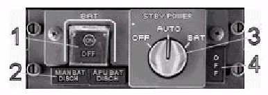
1- Battery Switch: Controls application of batter power to
the system.
バッテリースイッチ : システムへのバッテリー電源を制御します。
2- Battery Discharge Light: Illuminates when the main battery is being
discharged.
バッテリ放電ライト : メインバッテリーが放電中に点灯します。
Normally the battery is charged from the
Right Main AC Bus and this light is extinguished.
通常、バッテリは右側のメインACバスから充電され、このライトは消えています。
2a- APU Battery Discharge Light: Illuminates when the APU battery is being
discharged.
APU電源放電表示ライト : APU電源が放電中に点灯します。
3- Standby Power Selector: Controls the power source for the Standby
Buses.
予備電源セレクタ : 予備電源への電源ソースを制御します。
4- Standby Bus OFF Light: The Standby Buses are not powered if illuminated.
予備バスOFFライト : ここが点灯しているときはスタンバイバスに電源が送られていません。
Some critical instruments will fail in this
case (ex. Standby flight instruments).
なにか、重要な機器が故障している可能性があります。(例:予備航行計器など)
Electrical System Controls
電気系統のコントロール

1- APU Generator Control Switch: Controls the APU GEN breaker.
APU発電機コントロールスイッチ(押し込み式 : APU発電機ブレーカを制御します。
2- External Power Control Switch: Applies and removes EXT PWR to the system
when pressed.
外部電源コントロールスイッチ : このスイッチを押して外部電源の使用、使用中止を行います。
3- Bus Tie Control Switches: Controls the flow of power to the Left and
Right AC Buses.
バスタイコントロールスイッチ : 左右のACバスへの電力の流れを制御します。
4- Main AC Bus Off Light: When illuminated indicates that the respective
Main AC Bus is not powered.
メインACバスOffライト : 点灯中は、それぞれのメインACバスに電力が供給されていないことを示します。
5- Utility Bus Control Switches: Controls power to the utility buses.
ユーティテリティバスコントロールスイッチ : ユーティテリティバスへの電力を制御します。
6- Generator Control Switches: Controls the power from the respective engine
driven generator.
発電機制御スイッチ : それぞれのエンジン駆動発電機からの電力を制御します。
7- Generator Drive Disconnect Switches: Physically disconnects the generator drive
from the engine when double-clicked.
発電機駆動切断スイッチ : ここをダブルクリックすると発電機をエンジンから切り離します。
Once disconnected, the generator is no longer
available for use and can only be reconnected
on the ground via the Ground Requests menu.
一度切り離されると発電機は利用ができなくなり、グランドリクエストメニューからグランドに要請しない限り再接続できません。
APU Controls
APUコントロール
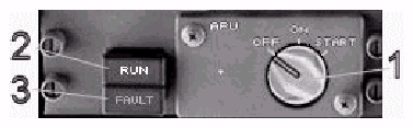
1- APU Selector Switch: Controls the operation of the APU.
APUセレクタスイッチ : APU操作を制御します。
Note that the Battery switch must be ON to
successfully start the APU.
APUのスタートを成功させるにはバッテリースイッチがONになっていなければなりません。
2- APU RUN Light: Steady illumination indicates that the APU
is running and is available to supply electrical
and pneumatic power.
APU RUN ライト : ここが点灯しつづけますと
APU が始動し電力と空気力が使用可能になったことを表しています。
3- APU FAULT Light: Steady illumination indicates an APU fault.
APU故障ライト : ここが点灯し続けているときはAPUに故障が生じています。
Momentary illumination indicates that the
APU fuel valve is in transit (during starting
and shutdown).
APU燃料バルブが作動するとこのライトは一瞬だけ点灯します。(スタートまたはシャットダウン中)
Electrical System Normal Procedures
電気システム通常操作手順
PREFLIGHT
飛行前
| Battery Switch - ON バッテリースイッチ ON Standby Power Selector - AUTO 予備電源セレクタ AUTO APU GEN switch - Pushed IN APU GENスイッチ 押してINにします。 Bus Tie Switches - AUTO バスタイスイッチ AUTO Utility Bus Switches - ON ユーティリティバススイッチ ON GEN CONT Switches - Pushed IN GEN CONTスイッチ 押してINにします。 APU - START then ON APU 起動してON位置にしておきます。 or または External Power - Establish (Press ON when AVAIL light illuminates) 外部電源 利用可能にします(ONを押す、AVAILライトが点灯します)
|
STARTING
出発時
| After start: 出発後 APU - OFF APU OFF or または External Power - Disconnect (Confirm ON and AVAIL lights extinguished) 外部電源 切り離し(APUがONであり、AVAILライトが消えていることを確認します) |
IN FLIGHT
飛行中
| No actions required for normal operations. 通常作業では何の操作も必要ありません。 |
POSTFLIGHT
飛行終了後
| Prior to gate arrival: ゲート到着前 APU - START then ON APU セレクタでSTARTし、セレクタON位置にします。 or または External Power - Establish (Press ON when AVAIL light illuminates) 外部電源を使用可能にします(外部電源ON、AVAILライトが点灯します) Complete Aircraft shutdown: 航空機の完全シャットダウン時 APU - OFF APU OFFにします。 or または External Power - Disconnect (Confirm ON and AVAIL lights extinguished) 外部電源 切り離し(ONを確認し、AVAILライトが消えていることを確認します) Standby Power Selector - OFF 予備電源セレクタ OFF Battery Switch - OFF バッテリスイッチ OFF |
| <<TOPページ | <Level-D 767 メニュー | <マニュアル目次 | <前のページ | >次のページへ |